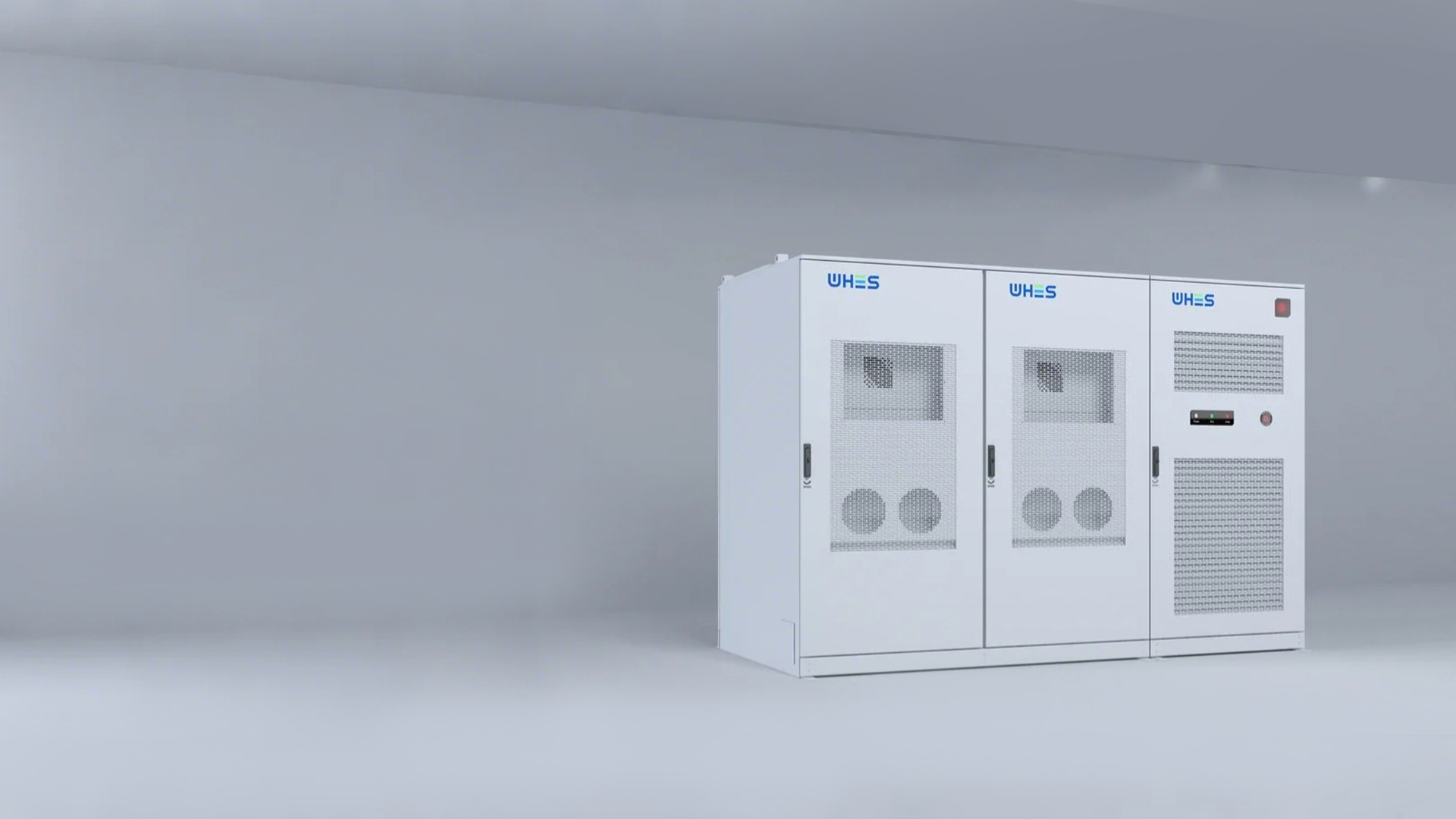
Opening the problem — why auxiliary consumption deserves attention
Auxiliary power consumption is often the quiet leak that erodes the apparent efficiency of battery-backed microgrids and commercial plants. When designers concentrate only on cell chemistry and inverter capacity, they can under‑estimate parasitic draws from control electronics, cooling systems and idle power stages — and the result is a lower round‑trip efficiency (RTE) than expected. Practical projects now routinely pair advanced commercial energy storage with hybrid inverters, but unless auxiliary loads are engineered down, the whole stack loses value. The California rolling blackouts of 2020–21 are a real‑world anchor here: they accelerated uptake of storage and showed how auxiliary losses affect system availability under stress.
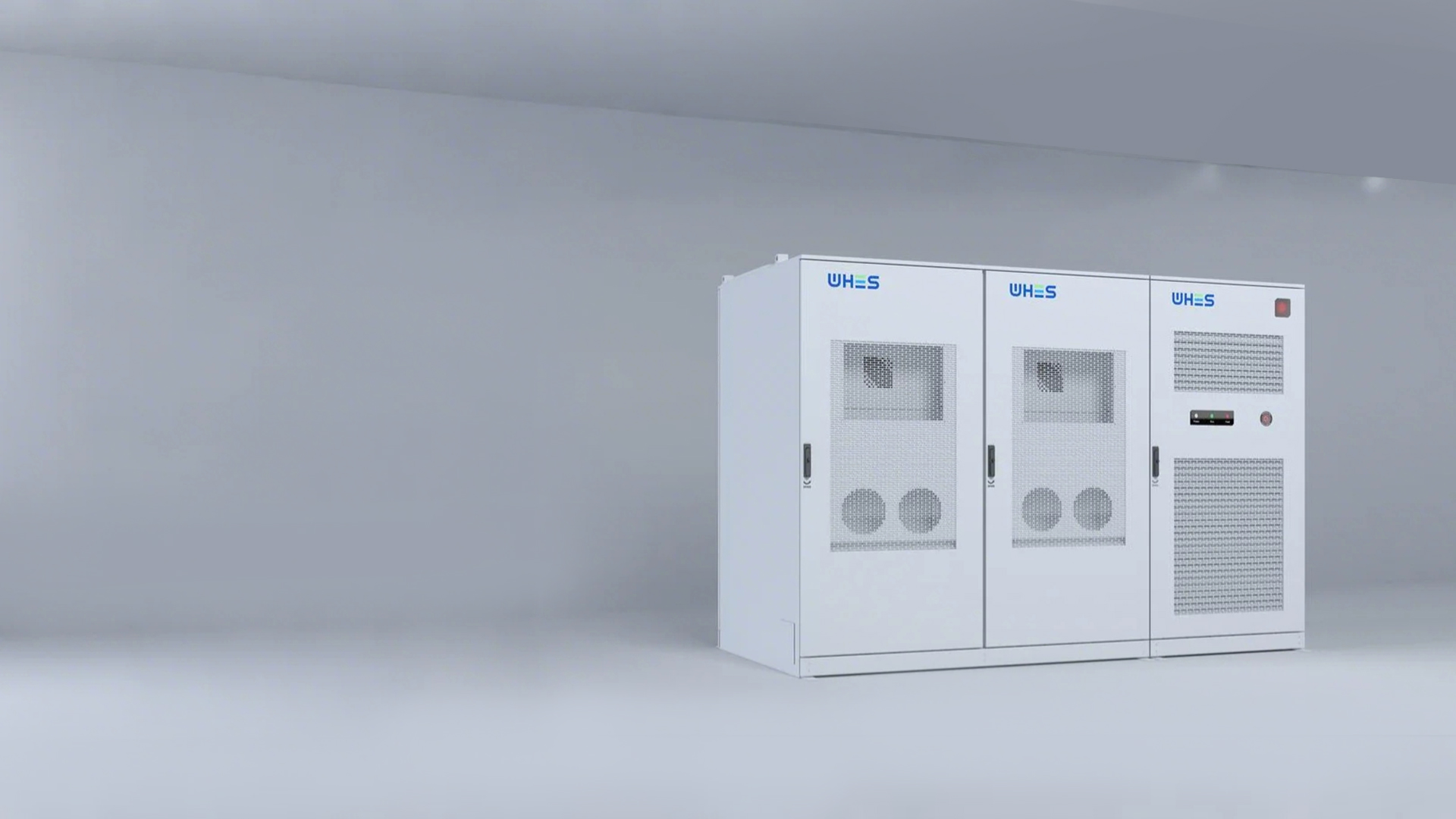
What “auxiliary consumption” really includes
Auxiliary consumption is everything the plant needs to run besides the primary DC–AC power conversion. Think control CPUs, gate‑driver supplies, fans and pumps, monitoring radios, and even transformer tap motors. Together they form the balance‑of‑plant (BOP) overhead. In practice, these items can add up to a few percent of installed capacity — not huge, but enough to matter for projects with tight payback windows or where guaranteed uptime is contractual.
Common engineering causes of excess auxiliary draw
Some frequent culprits are straightforward to fix; others need a re‑think of inverter topology or system architecture.
– Inefficient gate‑drive and bias supplies that run at fixed voltages regardless of load.
– Continuous running of large cooling fans because thermal margins were over‑specified.
– Auxiliary transformers or UPS systems that were sized without part‑load efficiency in mind.
– Control firmware that fails to enter low‑power modes when idle — and poor coordination with battery state of charge (SoC) management.
Addressing these issues often requires cross‑discipline work between power electronics, thermal engineers and controls teams — a detail many procurements miss. —
Design approaches to raise RTE in three‑phase hybrid inverters
Improving RTE is both component level and system level work. At the component level, use synchronous rectification and soft‑switching techniques to lower conduction and switching losses. At the system level, select an inverter topology that allows parts of the power stage to sleep when load is low, and implement dynamic fan control and selective bias supply gating. Good controls also align inverter idle behaviour with battery SoC and forecasted dispatch windows, so auxiliary systems don’t run full‑tilt overnight.
Monitoring, controls and the role of firmware
Granular telemetry is essential. Without per‑subsystem metering you can’t tell whether losses are thermal, control related, or mechanical. Implement local power meters for the inverter logic, the cooling loop, and any persistent auxiliaries. Build control states that include low‑power standby and maintenance modes, and make them visible in the operator dashboard. This lets engineers quantify savings after a firmware release — and it creates a feedback loop for continuous optimisation.
How to choose systems and suppliers
When evaluating hybrid inverter and storage suppliers, insist on three concrete demonstrations: measured no‑load auxiliary draw, partial‑load RTE curves, and a plan for firmware updates. If you’re procuring integrated units or modular stacks, consider deploying certified industrial battery storage systems that publish these metrics — it saves arduous field validation later. Also check for modularity so you can replace an inefficient subassembly without changing the whole bank.
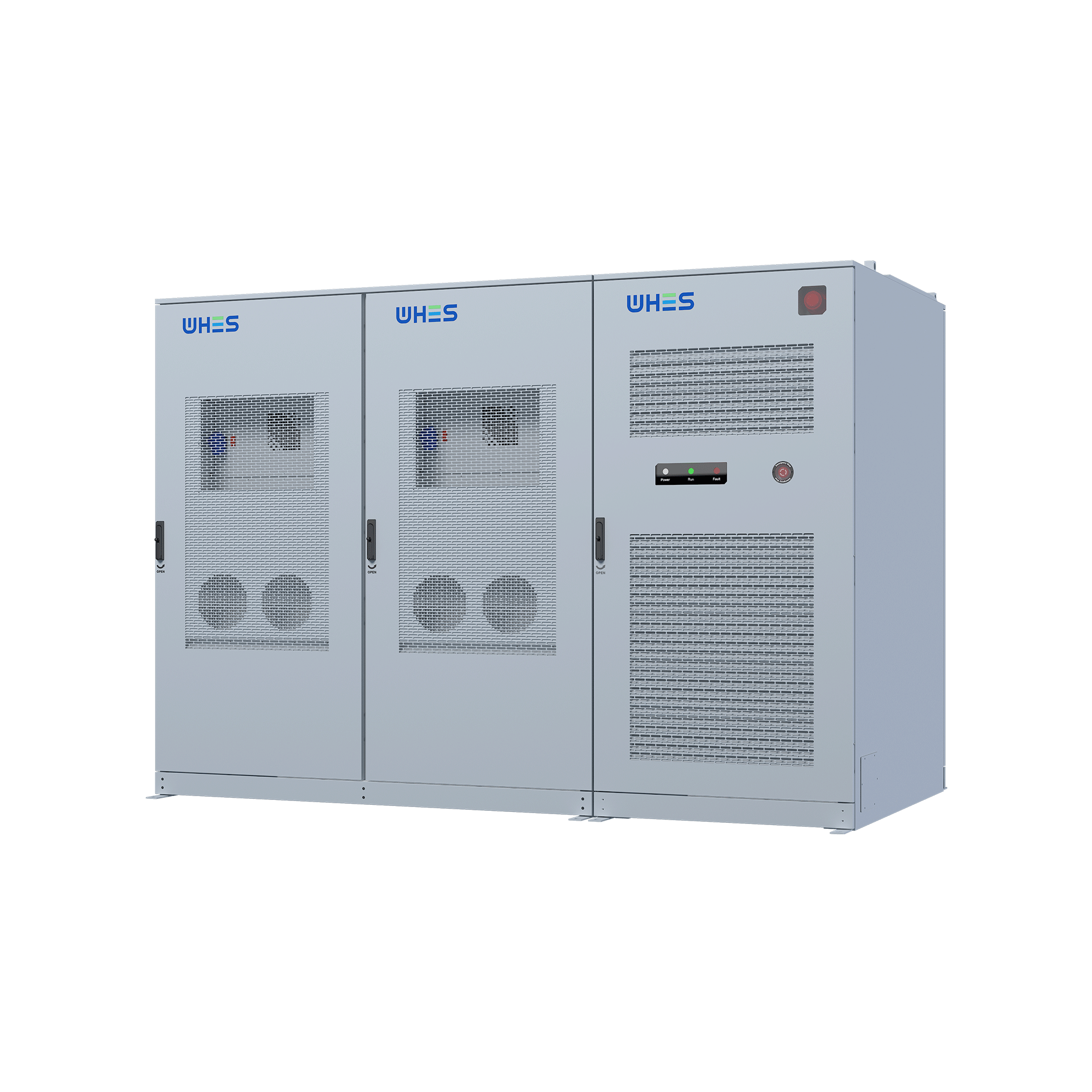
Deployment lessons and common mistakes
Teams often over‑specify cooling to be “safe” and then pay for it in operational loss. Others forget to test the actual fill‑level and SoC scenarios that the plant will see — so the inverter never gets the chance to enter efficient low‑power states. Integration tests with the final balance‑of‑plant and the control centre are non‑negotiable. Finally, don’t assume vendor datasheets reflect field reality; require factory acceptance tests under representative partial‑load profiles.
Advisory — three golden rules for selecting the right strategy
1) Demand measured, not modelled metrics: require no‑load auxiliary power and partial‑load RTE curves from suppliers. 2) Prioritise controllability: choose systems whose firmware supports sleep modes, dynamic cooling and remote updates. 3) Size holistically: account for auxiliary consumption in your financial model and warranty terms so payback and availability projections remain realistic.
These rules reduce surprises during commissioning and maximise the practical value of the storage‑inverter stack. Organisations keen to secure dependable, efficient solutions often find that vendors with transparent test data and modular designs deliver the best long‑term outcomes — and that’s where thoughtful engineering meets commercial prudence. WHES. —