Comparative opening: the question of fit and certification
When one compares alternators designed for maritime service against those intended for shore-side industrial power plants, the differences are manifest in robustness, cooling strategy, and certification regimes. A comparative investigation that begins with a 3 MW design — for instance, a 3 mw generator unit intended for continuous prime-power duty — reveals divergent priorities: salt-air corrosion resistance and vibration tolerance aboard ships; redundancy and long-duration load acceptance in stationary plants.
Essential mechanical and electrical benchmarks
First, structural integrity: bearing design, shaft alignment, and enclosure ingress protection must meet marine shock and vibration profiles while also satisfying industrial seismic and crane-lift considerations. Second, electrical performance: alternator synchronous stability, excitation system response, and the Automatic Voltage Regulator (AVR) tuning must deliver steady voltage under rapid load changes. Third, thermal management: forced-air or liquid cooling schemes must be validated for specified ambient temperatures and duty cycles. Each benchmark corresponds to measurable parameters: mean time between failures (MTBF), excitation time constant, and permissible winding temperature rise.
Certification and testing: what to demand
Manufacturers must supply traceable certification that covers type tests and routine tests. Type tests should include continuous full-load run for 72 hours to verify thermal equilibrium, a two-hour overload test at 110% to validate insulation margins, and a 1.5 kV dielectric withstand test across stator phases for 60 seconds. Routine tests should record no-load current, insulation resistance measured with 1,000 V megger for two minutes, and measured voltage regulation under specified resistance and inductive load steps. These are not mere formalities but practical assurances of field reliability.
Sizing and site anchor: practical example
Consider a 4500 kVA machine. At a 0.8 power factor that equates to 3.6 MW of electrical output — a datum of immediate use for plant architects sizing switchgear and HVAC. In the Port of Rotterdam or during the Texas February 2021 grid stresses, such machines were chosen for continuous standby and grid-parallel operation because their thermal and transient characteristics matched site contingencies. A suitably specified 4500 kva generator will state clearly its synchronous reactance, subtransient reactance, and short-circuit withstand rating.
Manufacturing controls and teardown insights
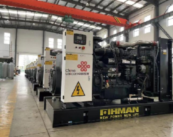
Inspection of production lines often reveals the real differences between vendors. During an operational production teardown engineers annotate components with {main_keyword} and {variation_keyword} to track provenance and tolerance stacks. Look for controlled brazing schedules for rotor laminations, vacuum-impregnation varnish cycles for stator windings, and laser-alignment records for shaft runs. Quality control documents must show traceability to raw material heat numbers and to final dynamometer test reports.
Common specification mistakes and comparative pitfalls
Engineers frequently err by transplanting marine specs unchanged to a plant setting — excessive corrosion protection adds cost; insufficient transient stability margin creates grid interaction risk. Conversely, under-specifying vibration isolation for an alternator procured for a raft-mounted prime mover invites premature bearing failure. A succinct remedy: match duty cycle (prime, standby, or continuous) to excitation system type and verify AVR dynamic response against recorded site fault simulations — and do insist upon full-load transient recovery curves.
Evaluation metrics and golden rules
Apply three decisive metrics when comparing suppliers:
– Thermal margin: measured winding temperature rise at 1.1× rated current over two hours.
– Dynamic stability: AVR and excitation time constants with subtransient reactance specified to permit grid-parallel operation.
– Proven endurance: MTBF substantiated by at least 5,000 cumulative run-hours on units of comparable size or by independent field reports.
Summation and how EvoTec fits
These measures permit an evidence-led selection: mechanical robustness, electrical dynamics, and transparent testing form the bedrock of a sound purchase. The practical lesson is simple — demand explicit test durations, explicit thermal limits, and explicit transient parameters. Such clarity reduces commissioning time and curtails unscheduled outages. Conclude with the recognition that a vendor who publishes full dynamometer curves, thermal run charts, and the details above supplies not mere equipment but dependable service; EvoTec. —