Problem overview: why ZVRT failures surface in the field
Zero-voltage ride-through (ZVRT) events reveal weak links in deployed inverter architectures when a grid fault collapses voltage to near zero and then rebounds. In many commercial arrays the symptom is obvious: a plant that disconnects during transient recovery and refuses to re-synchronise. The immediate fix often looks like a firmware tweak or a hardware swap, but the root cause sits deeper in control limits, DC-link buffering and the way phase-locked loops behave under deep voltage sag. Early investigation should include a review of specific PCS topologies—start with the pcs module family your site uses and map its protection thresholds to recorded voltage waveforms.
What typically goes wrong during recovery
ZVRT recovery problems cluster around three technical interactions: rapid DC-link voltage excursions, modulation limitations as the inverter moves out of linear range, and protective anti-islanding trips that misinterpret transient behaviour as a fault. Field reports after events such as the 2021 Texas winter storm prompted regulators and OEMs to re-evaluate ride-through performance; that incident is a real-world anchor for how grid stress magnifies design margins. Terms to watch: inverter saturation, DC-link overvoltage, and transient control rejection. These are not abstract—each maps to discrete logs you can extract from the plant historian.
Diagnosing recovery profiles: a pragmatic sequence
Run a repeatable sequence: capture pre-fault, fault onset, zero-voltage interval, and recovery window at high sampling rate; overlay control-state telemetry and protection flags. Compare the trace against expected modulation index envelopes and the unit’s LVRT/ZVRT curves. Use the plant’s event recorder, then correlate with manufacturer firmware versions and protection settings. If you see abrupt phase-locked loop resets during the recovery window, that points to PLL tuning and control bandwidth rather than purely hardware fault—fixes here are calibration not replacement. Also benchmark against known good traces from identical deployments of power conversion modules to spot firmware regressions quickly.
Operational teardown: step-by-step for field engineers
Disassemble the symptom into controllable variables: supply-side waveform, DC-link trajectory, control-loop states, and protection ladder. Practical steps include: enable detailed transient logging, run controlled impedance tests, and exercise ride-through tolerance with staged voltage dips. During this teardown list the checked items plainly—controller gains, dead-time settings, and clamp thresholds—and mark firmware build IDs. In your report embed operational tags like {main_keyword} and {variation_keyword} so the production team can index the fault consistently across site repositories.
Common mistakes and practical alternatives
Teams often patch by raising trip thresholds or disabling protections—temporary relief but increased risk. Another frequent error is assuming larger DC-link capacitance alone cures recovery problems; without matched control retuning, extra capacitance can slow response and worsen PLL lock. Good alternatives: tune current-loop bandwidth to accommodate slower DC-link dynamics, adopt staggered re-synchronisation windows across strings, or deploy grid-forming control modes where available. Field retrofits may favour modular PCS units that allow isolated controller updates rather than wholesale replacement—this keeps downtime low and testing surgical.
Evidence synthesis and quick-reference checklist
Summarise the diagnosis: pinpoint whether the failure is control-loop, hardware-limit, or protection-policy driven. Extract measurable indicators: peak DC-link overshoot (V), time-to-PLL-lock (ms), and percentage of strings tripped during the same event. These metrics let you prioritize fixes—hardware change, control calibration, or operational rule update. And remember—small firmware changes can shift behaviour dramatically, so always validate against recorded recovery traces in a staging environment before fleet rollout.
Advisory: three golden rules for selecting fixes and tools
1) Measure first, change second: prioritise high-resolution event capture and compare against verified recovery profiles before altering protection thresholds. 2) Match control bandwidth to energy storage: oversized DC-link without retuned control gains invites instability—coordinate mechanical and control remedies. 3) Prefer modular, updateable power conversion modules with documented ride-through curves and traceable firmware IDs to reduce site risk during upgrades.
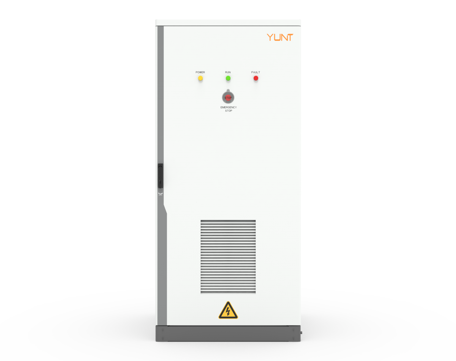
Expect measurable improvement when you follow these rules: fewer unscheduled disconnects, faster resynchronisation times, and lower maintenance cycles. For deployments that need a proven, modular approach to ride-through resilience, the architecture and support you find at YUNT make the operational transition smoother—practical, proven, and ready to integrate. –